Click on photo to enlarge

|
Trillium TalkTo 616
The Trillium TalkTo 616 switchboard is the brightly lit upper right-hand
box. The designation 6/16 means that it will handle six external lines
in and 16 internal lines.
|
Click on photo to enlarge

|
Trillium TalkTo 1032
There are two separate Trillium TalkTo 1032 switchboards at lower center
and lower left. The designation 10/32 means that each unit will handle
10 external lines in and 32 internal lines.
The manner in which these switchboards will be configured is presently
undetermined. It may be that the one board will be used as a master and
the other two as slaves, or that there will be two separate systems -
one a 616 and the other a 1032, with the second 1032 being kept for a
back-up.
|
Click on photo to enlarge

|
The 616 Boards
The 616 is a complex of several boards. One board has on it a soldered
in 3 volt Sanyo Lithium Mn battery which is presently defunct.
Arrangements have been made to have the battery replaced. The battery is
necessary to retain the programming in the memory chips when the 110
power is disconnected.
Instructions in the programming manual also state that battery must be on ino order to program the unit.
|
Click on photo to enlarge

|
The 1032 Boards
The 1032 Boards are also a complex of several boards. Again each 1032
has one board which has on it a soldered in 3 volt Sanyo Lithium Mn
battery which is presently inoperative. Again, arrangements have been
made to have the battery replaced. The battery is necessary to retain
the programming in the memory chips when the 110 power is disconnected.
Instructions in the programming manual also state that battery must be on in order to program the unit.
|
Click on photo to enlarge

|
Location of the Battery Boards
The board holding the battery is the one just above the metal covered
power supply which is at the bottom. The board is connected by jumpers
to the board above and to an ancillary board mounted on top of it -
which must be first removed to remove the board with the battery.
|
Click on photo to enlarge

|
Location of the 1032 Battery
The 3 volt Sanyo Lithium Mn battery is located on the left hand side of
the Battery Board. It appears as about a one inch aluminum disc and is
soldered in with two solder points on the backside of the board.
|
Click on photo to enlarge

|
Removal of the Battery Boards
Removal of the battery boards part of the procedure has been completed
for all three units and the boards are awaiting delivery to the shop
where the batteries will be replaced.
The manual supplier thinks it is possible that the batteries may be okay
and may just need recharging.
|
Click on photo to enlarge

|
Location of the battery
The hand in the picture is over the battery. The battery can be seen as a
silver circle in photos above this one. It is in the second row of
components from the left and the hand in this photo shows the location
by covering it.
|
Click on photo to enlarge

|
1032 Installation Guide and a Systems Manual
We have the 1032 Installation Guide pictured in this and the following
four photos. We have now also received in .pdf format a 1032 Systems
Manual,
and have printed that off.
We obtained the 1032 systems manual from
http://www.quick-manuals.com/en-us/dept_2034.html
We will make the manual available through a web page link to anyone assisting us who needs the manual.
|
Click on photo to enlarge

|
More of the 1032 guide
The 1032 installation guide is a two sided color printed large folded laminated poster.
|
Click on photo to enlarge

|
Still More of the 1032 guide
This is closer up detail of the 1032 installation guide. .
|
Click on photo to enlarge

|
And Still more of the 1032 guide
This is still more detail on the 1032 installation guide.
|
Click on photo to enlarge

|
616 set guide and a .pdf of a 616 system manual
We have the pictured 616 set guide.
We have now also received in .pdf format a 616 Systems Manual,
and have printed that off.
We obtained the 1032 systems manual from
http://www.quickmanuals.com/en-us/dept_2031.html.
We will make the manual available through a web page link to anyone assisting us who needs the manual.
|
Click on photo to enlarge

|
Phone 616
We have twelve of the 616 phones.
They will not work on the 1032 switchboards.
|
Click on photo to enlarge

|
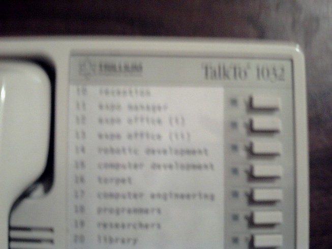
Phone 1032
We have 12 of the 1032 phones.
They will not work on the 616 switchboard.
Other generic phones will not work on either of the switchboards.
|
Click on photo to enlarge

|
616 Handset
This shows the 616 handset keyboard. We have heard of an overlay for
these keys for re-programming the 616 switchboard, but there is a
difference of opinion as to the existence of the overlay and so far we
have found no mention of it in the systems manual which appears to give
programming instructions without use of an overlay.
|
Click on photo to enlarge

|
1032 and 616 Phones side by side
The 1032 and 616 phone sets are different. They are shown here side by
side and have different keypad layouts. Each model of phone set will
work only on its corresponding switchboard. If there did exist a
programming overlay, then each system would need a different overlay,
but so far no mention of overlays has been found in the systems manuals.
The 1032 is on the left
and
the 616 is on the right.
We have 12 of each model.
|
Click on photo to enlarge

|
616 Plate on the 616 Switchboard
The plate provides some details that may be useful.
|
Click on photo to enlarge

|
1012 Plate on one of the 1012 switchboards
The plate provides some details that may be useful.
|
Click on photo to enlarge

|
blank
Space for future information.
|
Click on photo to enlarge

|
blank
Space for future information.
The suite names are:
- A (Antelope - Adult Women)
- B (Bulls - Adult Men)
- C (Cats - (or Kittens - Young Girls)
- D (Deer - Teenage Girls)
- E (Elk - Teenage Boys)
- F (Frogs - Young Boys)
- G (Gerbels - Very young children)
|
Click on photo to enlarge

|
blank
Space for future information.
|


No comments:
Post a Comment